| #project__hexo, #hardware, #electronics, #project, #design | |||
Hexo - Prototyping, Design, Simulation |
|||
Pictured above is a printed circuit board or PCB. Dubbed Hexo, a play on the prefix hexa-, meaning having six, it’s an electrically random “six-sided” die. I like to call it “electrically random,” because that sounds cool, and because the LED which lights up at the end is an output of a function whose inputs are voltages and time. When you push the button, Hexo cycles through its six LED, slower and slower, until eventually leaving just one LED on.
I built Hexo because I wanted to learn how I should go about bringing something into existence… something inanimate, that is. What I’m left with is a kind of systematic process that I hope will allow me to build bigger and more ambitious projects in the future!
This is what I’ve discovered so far; electronics projects like this can be broken down into the following steps:
- Requirements Gathering
- Prototyping, Analysis, & Simulation
- Schematic Capture, Mechanical Design, & PCB Layout
- Manufacture & Parts Ordering
- Assembly
- Validation, Testing, & Integration
In this post, I want to share with you my experience with prototyping, design, and simulation, the steps centered around implementing functional design. So grab a cup of tea or coffee and let’s geek out!
Prototyping, Analysis, & Simulation
I didn’t design Hexo’s primary circuitry; the design came from 555 Timer Circuits’ Roulette schematic and the many derivatives thereof. With a few very minor modifications, I was able to turn their 9-volt, 10 LED design into a 3-volt, 6 LED design with a similar effect. To read more about that circuit and how it works, you can read my writeup on Hackaday here.
With that said, in order for me to understand how to modify the circuit and to measure its performance, I had to build prototypes, do some pen-and-paper analysis, and (although perhaps a bit overkill), employ the use of circuit simulation tools. These things all happened in a happy nonlinear feedback loop during multiple iterations.
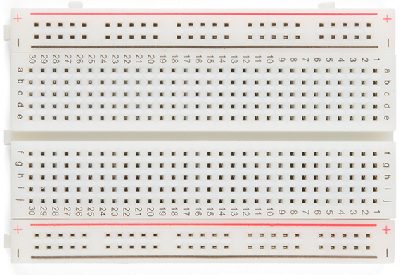
For prototyping, I use these things called breadboards (also known as solderless breadboards, it got its name from the old practice of using nails hammered into a cutting board to wire up temporary circuits), pictured below. A breadboard allows you to quickly “plug in” a bunch of through-hole (or THT, through-hole technology) components and test out designs.
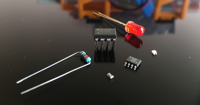
Below, you can see a few THT components next to their equivalent SMT (surface mount technology) counterparts, which are often used on PCBs because of their small size. You can probably guess why it’s easier to prototype with through-hole components, though they aren’t only used for prototyping!
Prototyping in this way allows you to take the circuit off of the page and place it in your hands in order to answer questions like: “does this even work?”, and “is it supposed work like that?”, and “ugh… why isn’t this working?”, usually followed by, “oh wow, how am I such an idiot?” (I put in the LED backwards… again.)
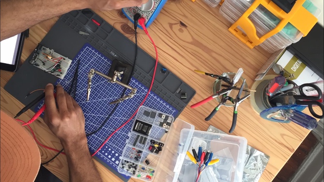
Having a small country’s worth of components sitting around is the only way I’ve seen electronics hobbyists get through prototyping. (That’s why a lot of us join a hackerspace, a physical place where geeks unite and stockpile their trove of parts and tools). Before I set off on my electronics journey, I invested quite a bit in building out a workbench and I have more than enough to share!
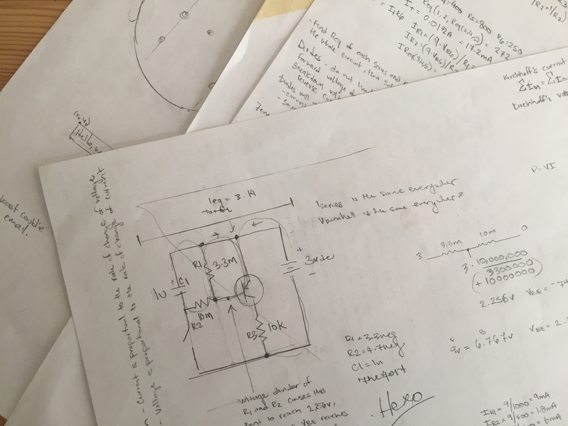
If prototyping is taking a circuit off of the page, then circuit analysis is… writing more stuff on the page? Analysis allows you to understand the mathematical theory behind the circuit. Equations derived from the Laws of Ohm and Kirchhoff allow us to understand idealized circuits, that is, how the design would function in a vacuum without interference, resistive wires, and perfect electron flow. Combined with higher-level patterns, one can begin to read circuit diagrams, called schematics, like lead sheets and fake books in the world of jazz or design patterns in the world of code writing.
Having not formally studied electrical engineering, this was one of the more exciting parts of this build. I love seeing theory on the page become measurable and observable in real life. This is the part where we use math to affect decisions about design. It turned out that even though I was switching from using a 9-volt battery to a 3-volt battery, I didn’t need to change any of the other components in the circuit.
Lastly, simulation. Using CAD (computer aided design) software allowed me to more easily and efficiently do circuit analysis; particularly with circuits that contained integrated circuits, or the little black things that look like microchips.
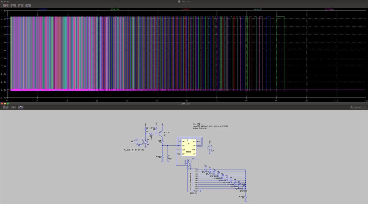
This is where I learned about SPICE: Simulation Program with Integrated Circuit Emphasis, and its variants like LTspice, pictured above.
SPICE uses, what I’ve only seen described as, an ASCII-based declarative language to define component models, netlists (how components are connected), and initial condition directives to calculate the electrical state of a given circuit. In Hexo’s case, I used a transient analysis, which allowed me to observe the circuit’s behavior over time. This was particularly useful given that the LEDs would blink, and “blinking” is a function of time.
Pictured above, the top half of the image shows the state of each of the ten LEDs, in that particular Hexo iteration, plotted over time. Taken as a whole, you can see how the rate of flashing (defined by the period and duty cycle of the square wave) begins to slow or stretch out over time as the LEDs blink and cycle slower and slower, before ending with only one remaining lit.
I’m really excited about SPICE. I’m not sure where it sits in the professional electronics industry, but there’s not a lot of documentation for us mere hobbyists. I hope that we, as a maker community, can work together to change that.
A more intuitive type of circuit simulation can be done using the Falstad Circuit Simulator.
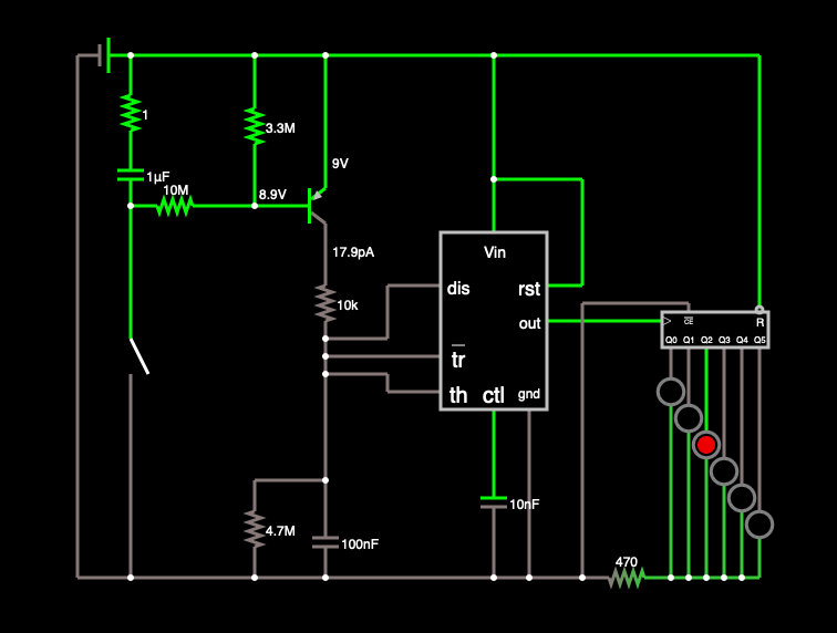
In fact, if you want to play with Hexo, you can take a look at the simulation with Falstad’s free browser-based app here. Although Falstad’s models are less realistic in a few ways, the drag-and-drop interface, the current flow visualizations, and real-time interactivity helped me build up a more intuitive understanding of Hexo’s design.
From bench, to paper, to screen. Back and forth, I’ve iterated and studied Hexo’s design until I felt confident that the circuit would work after I tweaked it a bit. I imagine a similar, if not more rigorous, process would exist for building an original design as well.
Now that we’ve experimented with prototypes and understood the theory, it’s time to design the physical thing!